• Thank you for visiting HeavyEquipmentForums.com! Our objective is to provide industry professionals a place to gather to exchange questions, answers and ideas. We welcome you to register using the "Register" icon at the top of the page. We'd appreciate any help you can offer in spreading the word of our new site. The more members that join, the bigger resource for all to enjoy. Thank you!

580SE Power Shuttle Fluid Question

bowen

Senior Member
Joined
Nov 13, 2011
Messages
540
Location
N. GA USA
Occupation
Electrical Panel Builder
There is a engine turning tool you can purchase from Case or Snap On # YA9565A - they are slow, but makes it real easy
I had found the Case tool # CAS1690A from Coleman for like $45, but online it says "discontinued".
Snapon online says $65 maybe. I would like to have one. Also good when getting the hyd pump coupling off.

I am going to find that plug, get the oil changed and then work on the other later to be sure the leak is really the control valve.
I have other issues. The neutral switch must be jumped out because it will start in gear.

Solenoid_480_11-25-11 006.jpg

Also the clutch solenoid button on the bucket lever does nothing. I need to get all this cleaned so I can find the parts.
I am surprised to read that the clutch solenoid just "screws off".
Shuttle.gif

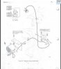
I suppose I would need the o-rings item 50. I already ordered 43 & 49.
I do not know yet if I need a new solenoid or have a wiring problem. My fuel tank shutoff valve was leaking pretty bad and fuel was all over the shuttle area.
Right now I have all the air box assy off, all cleaned and painted, and plan to remove the fuel tank to clean and paint it. I have new valves ordered for the tank also.

Thanks for the help, and I sure need it. :D
 

bowen

Senior Member
Joined
Nov 13, 2011
Messages
540
Location
N. GA USA
Occupation
Electrical Panel Builder
That Darned Torque Converter Drain

Torq_Conv_Drain_Plug_480_12-5-11 007.jpg Power_Shuttle_336_12-5-11 001.jpg Shuttle_Screen_336_12-5-11 009.jpg Shuttle_Cover_336_12-5-11.jpg

Well thanks to the help I FINALLY found the little rascal.
I put a mark on the front pulley, and every time I got underneath I put a numbers on the TC with a sharpie. Finally at my # 12, I found the tiny 1/8" pipe plug, just like I was told. 11mm socket

I think I was turning the engine too much at the time, and going past the plug.
I got about 2 qts out of the TC, making just shy of 2 gallons out total. I actually spilled maybe a pint.

So now I put standard Hyd oil in from Tractor Supply right? ($45) Or to I buy the Case Hytran Ultra that is $95/bucket?

I have decided I don't like this heat up procedure; that's when my control valve leak showed up, locked down in 4th gear with full throttle for 40 seconds...

BTW it's HARD to get a picture of that plug! It's at least 2" up inside the dark housing hole and the flash does nothing. I finally put a pen light in at an angle to get this fuzzy photo.

It's amazing what all you can learn if you know nothing to begin with about something.
I am used to working on mowers, 4-wheelers, and 2 cycle engines.

Thanks again.
Benny
 

bowen

Senior Member
Joined
Nov 13, 2011
Messages
540
Location
N. GA USA
Occupation
Electrical Panel Builder
From the picture I posted on 12-5-11 you can see a fitting with wires up above the large solenoid. It has a wire on it plus I have a cut wire hanging down.
I I have determined this may be a Backup Alarm swiitch. Must close just in reverse. The switch looks similar to the neutral switch on the drawing.
I did not know I had a backup alarm at all IF this is what the switch actually is.:confused:

It's a real simple circuit with key switched 12VDC on the switch, and then the circuit goes directly to the alarm.

My question is this:
WHERE do they put the actual alarm, buzzer, beeper, or whatever it is.
So far I have not came across one at all.
Is the thing hidden someplace?:eek2
 

GWS

Well-Known Member
Joined
May 21, 2011
Messages
154
Location
Oklahoma
On my 580c the backup alarm is under the floor panel on the left seat belt mounting bolts. Not sure if that is where yours is.
 

bowen

Senior Member
Joined
Nov 13, 2011
Messages
540
Location
N. GA USA
Occupation
Electrical Panel Builder
On my 580c the backup alarm is under the floor panel on the left seat belt mounting bolts. Not sure if that is where yours is.

Did it look like either of these 2 options?

580SE_Backup_Alarm.gif
It's not clear where the alarm mounts.
They just call them "round" style or "rectangular".

Also, looks like some machines have a limit switch vs. the screw in style.
 
Last edited:

GWS

Well-Known Member
Joined
May 21, 2011
Messages
154
Location
Oklahoma
I have the same alarm and bracket but looks like it mounts differently. Mine mounts to the bottom of the floor plate or at least that is where I found it.
 

Attachments

  • Backup Alarm.jpg
    Backup Alarm.jpg
    30.6 KB · Views: 1,788

rbmiles1

Active Member
Joined
Dec 13, 2011
Messages
35
Location
CT
My question is this:
WHERE do they put the actual alarm, buzzer, beeper, or whatever it is.
So far I have not came across one at all.
Is the thing hidden someplace?:eek2

I had the floor out of my SE last weekend to repair the brakeline and I saw the alarm mounted center on the same cross member that the seat is mouted to.
 

bowen

Senior Member
Joined
Nov 13, 2011
Messages
540
Location
N. GA USA
Occupation
Electrical Panel Builder
Well I did get my control valve out today. A pipe wrench broke the solenoid loose and the thing screwed off easily.
Will the electrical plug go together backwards?
The snap ring is the kind I don't like because it has no holes, but I got it out.
On the other end I used a 1 7/16" + a 1 5/8" wrench for the fill tube, then a 7/16" ratchet for the 3 bolts.
The cover was stuck and when I tapped it with a hammer all the parts went in 4 different directions, but I think I found all the parts.
A ball, spring etc.
One photo here shows what is underneath the cover. Getting that ball to stick back in place will be fun. I suppose the ball sits inside the spring and into one of the holes.

When I got the valve cleaned up I can see rotational scarring in the center. Maybe .003" deep grooves, you can feel the wear with your finger. Will this be OK?
Tomorrow I may tackle taking this thing apart. So far I have not determined how to do this, but I hope to only remove one pin on the solenoid side.
Control Valve Removed_480_1-20-12 004.jpg Control Valve Removed_1-20-12 005.jpg Control Valve Removed_1-20-12 006.jpg Control Valve Removed_1-20-12 007.jpg Control Valve Removed_1-20-12 009.jpg

The bottom picture is the neutral swith: it's a tiny thing with a fixed ball in the center that presses in to make the switch.
The round plate with the ball detents just comes off, but has a groove that seats it into a certain position.

So far I can see only one o-ring that is on the outside of the control valve. The seal on the solenoid end is hard to see, but it's up inside the spring loaded end plunger.
 
Last edited:

melben

Senior Member
Joined
Jan 14, 2008
Messages
1,026
Location
Williamsport, Pa
Occupation
Retired 50 Yrs with Case dealership
You should not see the trans temp gage rise under normal operation, it is not mismatched , it is there to indicate an overheat condition. Proper operation can be verified by performing a stall test and heating the oil, no damage will result to a properly maintained and a reverser in good condition. It is the same syatem used through the 580K series prior to the phase 3 systems and reacts exactly the same, no indication under normal operation. Mel
 

bowen

Senior Member
Joined
Nov 13, 2011
Messages
540
Location
N. GA USA
Occupation
Electrical Panel Builder
You should not see the trans temp gage rise under normal operation, it is not mismatched , it is there to indicate an overheat condition. .... no indication under normal operation. Mel

I wonder what degrees they consider too hot?
I know that when I got my gauge up to barely decide it was working the oil cooler lines were almost too hot to hold. I would guess 110 degrees F.
I would still like to put a 10 ohm resistor in line with mine, or whatver resistance might be needed to rise it up a bit.
Are you a Case engineer? I hope you did not design this little lip seal that always leaks at the solenoid...

Control_Valve_Seal_480_1-21-12 002.jpg

This is easy to take apart. Drive out the small pin and pull out the parts.
The little seal fits into a groove and the little plastic tool is to compress the outside lip to get the plunger back inside the housing.

Mine just had one of the item 50 o-rings, This is on the outside and easy to replace.
I jusy hope that these worn places around the outside is not a problem.

I did not take the other end apart.

I'm sure most of you know this, but this spring loaded plunger is what goes up inside the solenoid.
The solenoid has a spring up inside that is stronger than this spring and it holds this one in, unless the clutch is energized.

My solenoid had some oil up inside it that I let drain out. I do not know if this is normal or not.
 
Last edited:

alrman

Senior Member
Joined
Jun 20, 2009
Messages
3,308
Location
QLD Australia
Occupation
Diesel Fitter;Small Business Owner;Cleaner
My solenoid had some oil up inside it that I let drain out. I do not know if this is normal or not.

Bowen, the oil content in the valve is normal. I usually flush the body with kero & while washing, continually depress the internal plunger to be sure it is not sticking, dry & then lube with a squirt of fresh oil from an oil can - make sure the bore where the seal sits is not rusted.

Don't know if you realise, the shuttles are designed by Borg Warner - not Case. They can be found in JCB, Chamberlain, JD, (with slight differences) & others I don't know about. I believe they are used in marine applications also.
 

melben

Senior Member
Joined
Jan 14, 2008
Messages
1,026
Location
Williamsport, Pa
Occupation
Retired 50 Yrs with Case dealership
Since the gage pegs when the wire is grounded - virtually no resistance- then it stands to reason that adding resistance to the circuit would compound the problem that you do not like. You would have to find a sender with LESS ohms as a starting point to accomplish what you want. You do realize that 110 deg. is just above body temp a few degrees and Case considers 100 deg above ambient to be an acceptable working temp for the main hydraulic system. The gage is designed to show you an overheat not a normal operating temp although the unit is in no danger working in the green. After a rebuild is off my bench and installed I lock it down in high gear and force the gage reading into the red at full engine throttle and then check clutch application to make sure of my work and to leak check. One of the last things to worry about is if that gage has an indication in normal operation. My advice for what it's worth is to put it to work, in normal day to day, tranny temp is a non issue.

Alrman is correct, the Borg Warner unit in question is the same as many other brands use. I have rebuilt JD 310 units right out of our Case parts books with the exception of the torque converter. There is a difference in the reverse plates but Case stuff goes right in and works in place of what Deere uses. Mel
 

bowen

Senior Member
Joined
Nov 13, 2011
Messages
540
Location
N. GA USA
Occupation
Electrical Panel Builder
Since the gage pegs when the wire is grounded - virtually no resistance- then it stands to reason that adding resistance to the circuit would compound the problem that you do not like.

You are exactly right Mel, I was thinking in reverse.:eek:ops
I measured the resistance on this sensor which was something like 6800 ohms at 55 degrees. So it ranges from near zero(hot) up to 6.8K thereabouts.
I could parallel maybe a 20K resistor across the sensor to manipulate the range from 0 to ~5K (vs 0-6.8k) , or maybe use a 15K resistor that would manipulate the range up to only ~4600 ohms.
This would bring the needle up some at all times, but screw with the heat curve which I am sure is a bad idea.

I likely will do nothing except know that if this gauge gets up 1/3 of the way I need to look at the oil cooler because something is abnormal.
Seems to me these machines are designed beefy to run cool even with some crap covering the grill as so often is the case in bad environments

When I had my oil cooler off & needed to crank the machine I put a 3 foot section of 1/2" semi-clear polyflo tubing in the hose fittings, letting the fluid circulate with no cooling nor resistance from the cooler tubes.
I was amazed at how fast the oil was circulating thru the tube whan I cranked the machine. I could also see that my oil was dirty even with some particles passing thru the tube at times.

I wondered during this if anyone changes the shuttle fluid at the oil cooler like this. Remove one hose coupling at the cooler and pump clean fluid thru the transmission, Torgue Converter and cooler all at the same time.
I know thay do this with automobiles and a pump saying it changes ALL the fluid...
I know this would not clean the screen, but it would have eliminated me finding that little TC plug.

Thanks for you input to help educating me. :bash
 

bowen

Senior Member
Joined
Nov 13, 2011
Messages
540
Location
N. GA USA
Occupation
Electrical Panel Builder
- make sure the bore where the seal sits is not rusted.

Contro_Valve_Seal_480_1-21-12 003.jpg Seal_Tooll_1-21-12 004.jpg

This was before I cleaned it up. I wanted a picture to see the orientation for how the seal came off.
You can see a bit of rust on the shaft which I polished a bit with some 600 grit sandpaper, just to protect the new seal sliding on.
Down in the goove it was pretty clean. The little seal is pretty tight sliding on because it's inside OD is a good bit smaller than this shaft.
For rbmiles the seal in the photo sits in the oily groove over to the left.

The other photo is the blue tapered tool as the plunger goes back in. It compresses the outside seal lip.
You can also the see the pin that I was starting to put back in.
That pin is the only thing holding this plunger in the valve.
Beside the pin is the other o-ring, item 50 in the parts list.

To hold that little ball on the spring when putting the cover back on I read someplace to use Vasoline(petroleum jelly).
I hope this is the secret cause it's hard to see up in there while laying on my back.

All_the_parts_480_1-22-12.jpg
This is everything involved ready to put back on I think.

Thanks again. I am now eager to get this thing back in and filled with oil. I am nervous we will have an ice storm with trees down all over the place and me with no backhoe.:eek:
 
Last edited:

melben

Senior Member
Joined
Jan 14, 2008
Messages
1,026
Location
Williamsport, Pa
Occupation
Retired 50 Yrs with Case dealership
Just a thought to add into the mix, The torque converter while running acts as a centrifuge and all the dirt would be thrown to the outside while the engine is running possibly making a running flush such as you describe a bit ineffective. Transmission shops used to have a fixture that the converters are put onto to introduce a cleaning agent to loosen internal debris. Anyone who works with the old 450 Case takeapart converters can attest to the gray sludge that accumulates in the converter that is so thick it needs to be scraped out. A simple plug removal and allowing the converter to drain on its own imho is about as effective as anything although I'm all for flushing the cooler and lines, Actually Case recommends new coolers as part of a rebuild but------------------------- . Mel
 

bowen

Senior Member
Joined
Nov 13, 2011
Messages
540
Location
N. GA USA
Occupation
Electrical Panel Builder
Well I am back home after getting the thing all back in. I'm tired, cold & frustrated.
I got it back together, filled it with oil and everything was OK until I tried to heat the oil up in 4th gear with the parking brake on.
I crawled under after I got the oil level full and seen this...

Leaks_Still_480_1-22-12 004.jpg

You can see that stream down from the end with that little lip seal.
This was after runnig for 15 minutes or so backing up forward etc.
The other side is fine, neutral switch, linkage etc.

The question I have now is about the solenoid. I did not get this as tight as it was before because there seems to be no stop in this direction.
Seems I am stressing the linkage doing this.
How do I hold the thing to get this tighter, and might THIS be the problem?

Also my clutch switches are not working but I can short out the button wire to operate the solenoid if you think this might help seat the little seal somehow.
I did not try this today...

I did use rubber grease on this seal & o-rings, Was THIS a mistake?

Is my housing possibly worn inside so that a new seal & o-ring will not stop the leak?
It was fairly easy to get out and back in, even with the new item 50 o-ring, not much resistance.

I am 95% sure I turned the lip seal the right way, with the lip going on first.

Everything seems to work great just this leak that is maybe about the same as before. Seems I do not have a leak so long as I don't try to "warm up" the oil.
This must build high pressure in the shuttle.
I was just warming it up to check the final fluid level.
 

alrman

Senior Member
Joined
Jun 20, 2009
Messages
3,308
Location
QLD Australia
Occupation
Diesel Fitter;Small Business Owner;Cleaner
Sure it's not coming from the breather? If not ......... pull it apart again.......... think how much quicker you will be at it this time......:D

You can tighten the solonoid better if you put the FNR lever into ...... reverse I think. That way the selector plate is on the stops. Same goes for undoing it - but in fwd.
 
Last edited:
Top