• Thank you for visiting HeavyEquipmentForums.com! Our objective is to provide industry professionals a place to gather to exchange questions, answers and ideas. We welcome you to register using the "Register" icon at the top of the page. We'd appreciate any help you can offer in spreading the word of our new site. The more members that join, the bigger resource for all to enjoy. Thank you!

EX120 Operators Switch Panel not working

Egetebee

Well-Known Member
Joined
Jul 2, 2019
Messages
110
Location
New England
Hi Everyone,
Hitachi EX120-3
The entire operators right-hand monitor & switch panel has just stopped working. It was fine in the morning, then a lunch break and afterwards the entire panel no longer operates, no lights, not throttle control, nothing.
Joystick controls work but not the monitor / switch panel.
I'd check fuses but cannot read (but only a few) the fuse panel cover to know which fuses do what.

Any advice is greatly appreciated.

Thank you,
EG
 

Egetebee

Well-Known Member
Joined
Jul 2, 2019
Messages
110
Location
New England
Thank you mg2361,
I've done as you've instructed and have found that with the machine running (idling):
Fuses 1-5 have source power (24v) on the inside rail and the fuses are good.
Fuses 6-13 Do Not have 24v source power (only 0.5v) on the inside rail
Fuses 14-19 have power 24v power and fuses are good.
Fuse 20 does not have 24v power (0.0v) on the inside rail.

I'm not sure if the entire fuse block is supposed to have source power when running or if some are unpowered until needed but as said fuses 6-13 do not have source power on the inside rail.
Is the fuse block power controlled by relays?

I'm really struggling to imagine what could have gone wrong.
Any advice from here is greatly appreciated!

Thank you again,
EG
 
Last edited:

Egetebee

Well-Known Member
Joined
Jul 2, 2019
Messages
110
Location
New England
Thank you skyking1,
I'm actually not sure how to search for a broken ground with regard to only half the panel not having source power. As you said, wouldn't the entire fuse block be dead and not just part of it with a ground issue?

Do you know if the entire fuse panel should have power when the machine is idling or if some of the fuses (6-13) should actually have no power until switched on?

I think (or hope) it may be something relatively simple for most fuses to have power and some not.

Can you say how I should begin to trace?

NOTE: I did replace the batteries a couple of weeks ago but it's been running and operating fine so haven't thought that this may be a part of the problem. Again the machine starts & runs with the key but no throttle control or gauges work.

Thank you again,
EG
 

skyking1

Senior Member
Joined
Nov 3, 2020
Messages
7,662
Location
washington
I think your first guess at a relay taking out those fuses might be a good one. I have a straight JD 120 I wonder if it has the same fuse panel?
I can take a picture midweek next week for you if you are still working on it.
,
 

Egetebee

Well-Known Member
Joined
Jul 2, 2019
Messages
110
Location
New England
nA5Jp3S.jpg

Fuse Panel Cover:
Unsure of what 1, 3, 4, 5, 6, 7, 8, & 9 say.

zpVwbbV.jpg

Fuse Panel: Bottom left is #1 : Bottom right is #11

v4mwsau.jpg

Machine is idling - Nothing working on the console but the key to start the engine

Side question: What does the [ M ] button (second from right) do?

Thank you all once again,
EG
 

mg2361

Senior Member
Joined
Jul 5, 2016
Messages
5,145
Location
Pennsylvania
Occupation
Equipment Mechanic
1 = SW Backup (1A)
3 = EC Motor (5A)
5 = Power On (1A)
6 = Switch Panel (5A)
7 = Valve Controller (1A)
8 & 9 = Solenoid (5A) (for the 2 pump displacement solenoids)

Do you have battery voltage at the alternator "B" post with the key on? They all get there voltage from the white wire at the battery relay through the 50A fusible link. Make sure you have battery voltage at that post and through the fusible link (key on). No voltage through the fusible link then that is your problem. If you have voltage through the fusible link I would expect a bad connection or splice somewhere between the fusible link and the fuse box.
 

Egetebee

Well-Known Member
Joined
Jul 2, 2019
Messages
110
Location
New England
Thank you mg2361!
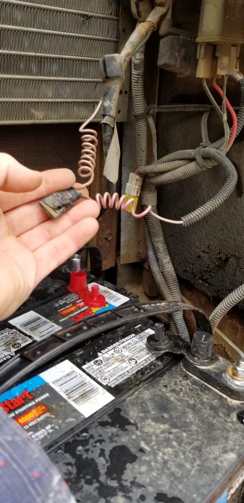
As instructed, I checked power from the alternator to the battery compartment and found a wire (tucked away) with a taped up inline 30Amp fuse that had blown. I don't know if this is the fusible link you mentioned but it was definitely bad. It does look like a modification as it's simply two female slot connectors plugged onto each leg of a standard ATO fuse; so what the original design was, I don't know.
dyASJy6h.jpg

Replaced the blown (30A) fuse with a 20A (that's all I had at the moment) and the operator panel came back to life (Yea!), however the 20A fuse blew immediately, yet the operator panel continued to work until I shut the machine down, then back to the same problem. Nonetheless, I'm really happy to have at least found a part of the issue and it's good to know that the fuse block and operator control panel are still good.

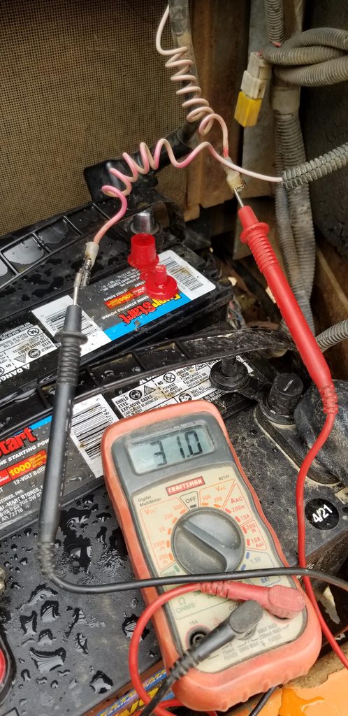
I then took the voltage between the wire connectors and found @ 30-32V (thus the blown 20A)
r6xHdtph.jpg


So now the question(s) are:
Is this the Fusible Link you mentioned even though it was 30A? If not, where is the fusible link?
Is this fuse supposed to be 30Amp? The machine has been running fine for years and so I'd think 30A is sufficient however not sure why it blew out the other day.
What would your approach be now; replace the 30A and see what happens or chase further to diagnose for a short?

Many, Many Thanks for this support as I feel much better about doing this repair.
Cheers,
EG
 

skyking1

Senior Member
Joined
Nov 3, 2020
Messages
7,662
Location
washington
The fusible link is much larger and on a big wire. This looks like somebody put in a" hyperspace bypass" jury rigging for some reason or another. It might be that the fusible link blew, and the previous owner didn't know how to fix that so he just put it in a small wire with an inline fuse.
I would not up that fuse in size beyond the 30 amp that blew, and also be cognizant of the wire size. If it is smaller than 10 gauge it's really not supposed to be supporting 30 amps.
Unfortunately you really need to trace that wire to both ends and figure out what they were thinking.
 
  • Like
Reactions: mks

Egetebee

Well-Known Member
Joined
Jul 2, 2019
Messages
110
Location
New England
Heheh, "hyperspace bypass"... gotcha. I've made a couple of those over the years too ;)

A clearer picture below:
Found the fusible link -> It seems to be within the small black box connected to the right leg of the battery relay (round device behind the metal shroud) along with the battery hot lead (24V). Not sure if I tested it correctly but there is 25+V on the wire coming from the back of the fusible link.

The wire in question (sun faded red / pink) with the 30A fuse also comes from the original OEM loom, then to the 30A fuse, then onto the left leg of the battery relay (has a splice to the blue wire / yellow connector)
UDiLFYvh.jpg

I've replaced the slot connectors with new but don't have a 30A fuse at the moment, will get some tomorrow.
As SK1 advised, I will Not up the amperage of the fuse but replace and see if it blows again, after which I'll chase the wire and look for a short.

Just found this:
There's a wire (Red Stars) that connects fuses 6-10 and I may assume 11-13 as well (which had no source power) that seems to be the one in question. I can't say I understand the schematic very well but the wire does look like it runs into 'something' on the battery side which I circled in red as maybe a fuse.
Can anyone verify this?
BCKkpDGh.jpg

Posted in case it helps someone else.

My son seems to think that the new batteries may have something to do with this problem and I might agree but it's been operating just fine since batteries were replaced nearly 2 weeks ago.
Checked the battery voltage which is between 26-28V

Any more input or advice is appreciated.

Thank again to all,
EG
 

Egetebee

Well-Known Member
Joined
Jul 2, 2019
Messages
110
Location
New England
mg2361, Nige, SK1 & All,
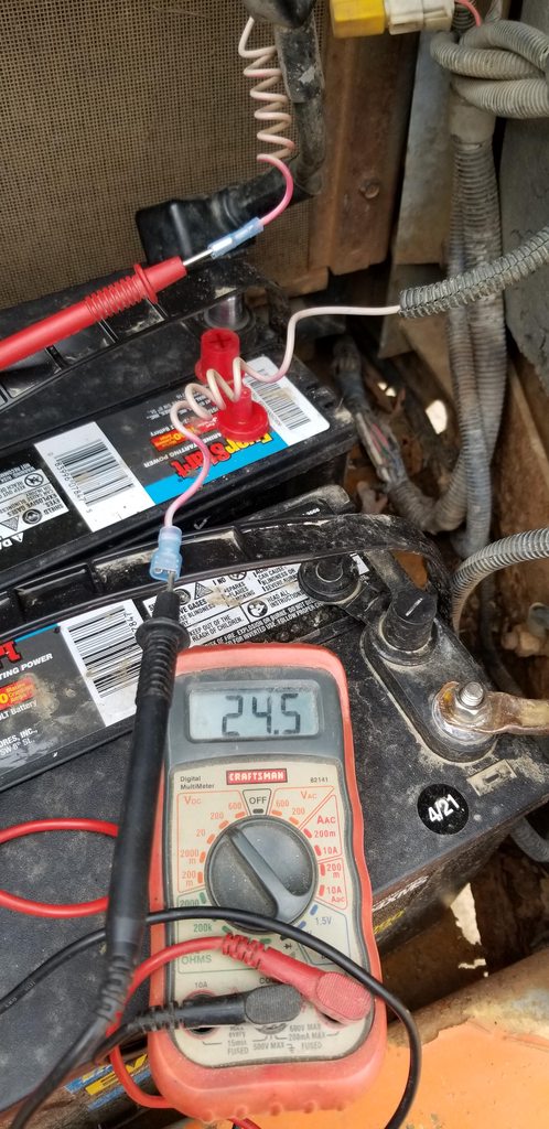
Based on your concerns, I took a voltage reading again after having replaced the slot connectors and found 24.5V.
I took the first reading (picture above msg:103) from the original connectors which were burnt pretty badly so maybe that had something to do with it.
80v9QMVh.jpg


Bottom line:
Installed a 30A fuse and the operator panel is now working properly with key cycling multiple times, seems stable.
I taped it up and tucked it away as to reduce rain exposure.


Thank you all so very much for your patience & support.
This machine is not getting any younger but works well around our property and having help in keeping it running is greatly appreciated.
Thank you again,
EG
 

skyking1

Senior Member
Joined
Nov 3, 2020
Messages
7,662
Location
washington
Digging mode
From bottom to top in your circled lights:
1: hoisting power for structures and the like
2: swing force for when you are stuck swinging uphill. Quit doing that :)
3)more power pushing away from you on the stick.
4) balanced forces and grading. Leave it there most times.
 

mg2361

Senior Member
Joined
Jul 5, 2016
Messages
5,145
Location
Pennsylvania
Occupation
Equipment Mechanic
I took a voltage reading again after having replaced the slot connectors and found 24.5V.

Looking at your picture of the meter reading (which I missed the first time) that is not the correct way to check voltage. The black lead from your meter should always be on a good ground, whether it be the frame or the battery negative post.
 

skyking1

Senior Member
Joined
Nov 3, 2020
Messages
7,662
Location
washington
Looking at your picture of the meter reading (which I missed the first time) that is not the correct way to check voltage. The black lead from your meter should always be on a good ground, whether it be the frame or the battery negative post.
I did not catch that! It is a good way to cook your meter, essentially you are potentially running the load through the meter. They have fuses but still not a good plan.
 

Egetebee

Well-Known Member
Joined
Jul 2, 2019
Messages
110
Location
New England
SK1, Thank you for the clarification of the [ M ] button.
SK1 & mg2361, Oh ok, right, I see what you're saying about taking voltage that way and will keep it in mind for the future. Black lead to ground, of course, didn't dawn on me.

Thank you again,
EG
 
Top