01Time
Well-Known Member
S/N: 5SZ07867
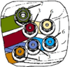
As mentioned in a previous post, I had a fire under the cab on my 246. I was finally able to get back out to my property and clean out the area a little bit. It definitely burned up some hoses and some wiring, along with the a plastic panel. I would really appreciate with some help with some parts identification.
I can't seem to find this on the Cat site and am looking for the part number of the item in the red box (it now has a big hole in it):

Also, are there part numbers for this wiring?

And is there a better photo out there of this (so I can figure out what exactly is gone and where it goes)?

I reached out to a friend of a friend who works on diesel engines and hydraulics who should be able to do the work/help me. But, I'd like to have the parts (most of them at least) ready when he's able to get out to my property. Any other advice is certainly welcome.
As mentioned in a previous post, I had a fire under the cab on my 246. I was finally able to get back out to my property and clean out the area a little bit. It definitely burned up some hoses and some wiring, along with the a plastic panel. I would really appreciate with some help with some parts identification.
I can't seem to find this on the Cat site and am looking for the part number of the item in the red box (it now has a big hole in it):
Also, are there part numbers for this wiring?
And is there a better photo out there of this (so I can figure out what exactly is gone and where it goes)?
I reached out to a friend of a friend who works on diesel engines and hydraulics who should be able to do the work/help me. But, I'd like to have the parts (most of them at least) ready when he's able to get out to my property. Any other advice is certainly welcome.