Shawn2jz
Member
- Joined
- May 8, 2020
- Messages
- 6
Hello guys! My name is Shawn and live about 45 minutes north of Baltimore MD.
I have been surfing the page trying to help a buddy with his 2012 CAT 246c skid loader which he recently purchased. His RH joystick for boom functions does not work.
First..I am a complete novice to working on a skid loader... However; I am pretty involved with automotive performance turbo applications/customization and have a nerd hobby of soldering/repairing circuit boards, SMD/IC chips etc.
So I feel fairly comfortable with troubleshooting/process of elimination.
His skid loader is serial number JAY06980. 2012 model. CAT 246C. Uses the Hydro-electric joystick controls .
The issue is his RH joystick is NOT operating the boom lift, bucket/tilt etc.
Everything else on the vehicle seems to be in working order. The skid loader starts, runs very smoothly and drives.
All of the interlocks DO seem to be working properly. Seat pressure, door, arm bar switch. Do work.
It does however have the flashing yellow driver alert (non-audible) which I gathered is a stage 2 fault?
Unfortunately, I do NOT have access to a scan tool and the machine also does NOT have the upper-RH display to display a code/fault.
I am curious if there is a pinout that may be possible to jump.. Similar to how obd1/obd2 ECM for automotive can be done to display a sequence of flashes to communicate a code?
The RH joystick, the thumb roller DOES bog machine down in both directions and the AUX Hydraulic lines DO jump.. So that portion does seem to be working.
I gathered up what I can so far on various pages to find schematics.. But am not 100% on the Values/specs that I should be looking out for.
I haven't had a ton of time to trouble shoot just yet..
However;.
So far.. I have tested on the RH Joystick 127-CH orange 12v b+ wire IS getting its voltage (12v off /14.3v when running)
And the 203-CH23 black ground wire has continuity to the chassis.
The other two wires.. On the 4 pin connector, BROWN wire and WHITE wire (which I read is the X and Y-axis signals to the ECM. I am unsure what values I should be seeing to test those..
I plan on atleast OHM testing each of the wires for the two separate harness connectors on the RH joystick to their destination points at the ECM .. To make sure there are no breaks in the circuits.
From the looks in a schematic I found.. It appears that the two signal wires (brown and the white) go to the ECM..
And then there is an output from the ECM to the solenoids on the Hydraulic pump? (I have not tested the solenoids yet either..and wasn't sure if I can just 12v directly to it for testing in fear it may cause damage to them.
I do NOT remember hearing the fan come on when I attempt to use bucket functions or even if I throttle the thumb wheel. I read something somewhere that mentions this is related to the Hydraulics.
The RH does NOT have any other functions.. No boom lift, tilt, etc from the RH joystick. I removed the joystick/sensor assembly and debated disassembling to see if i can find anything visually wrong.. But I'm wanting to hold out some until I can try some further diagnosis.
If anyone is willing and have the free time with any suggestions on what I should look out for or test.. Or possibly a good schematic/trouble shooting guide to help diagnose this issue. I would really appreciate it.
I feel that this is probably something very simple.. But I guess it's usually always the case.. It's finding that 'simple problem' that can be a hairy process... Especially being new to the platform.
WHEN the issue is diagnosed and repaired. I will be sure to follow up with atleast the solution, incase someone else runs into this issue.. In hopes that it can help them too one day.
I appreciate anything that you all are willing to do to help guide me!
Thanks,
Shawn
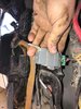
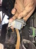
P.S.. Yesterday I found a large, Grey single relay cover under the cab (next to the main ECM) when just doing a test on all electrical connections (unseating/seating and checking for corrosion). Which they all seemed to be fine.
When I removed the cover.. I did NOT see a relay installed. It is a 3 pin female plug. Red/Green/Black Wires (look to be 10-12ga)..
I am not sure what this relay would control.. (possibly IGN/start the loader when the cab is raised for diagnosis purposes using a specific OEM CAT pigtail?.. I doubt it is related to the RH joystick.. But it was noticed . So I wanted to ask.. I attached an image of it
I have been surfing the page trying to help a buddy with his 2012 CAT 246c skid loader which he recently purchased. His RH joystick for boom functions does not work.
First..I am a complete novice to working on a skid loader... However; I am pretty involved with automotive performance turbo applications/customization and have a nerd hobby of soldering/repairing circuit boards, SMD/IC chips etc.
So I feel fairly comfortable with troubleshooting/process of elimination.
His skid loader is serial number JAY06980. 2012 model. CAT 246C. Uses the Hydro-electric joystick controls .
The issue is his RH joystick is NOT operating the boom lift, bucket/tilt etc.
Everything else on the vehicle seems to be in working order. The skid loader starts, runs very smoothly and drives.
All of the interlocks DO seem to be working properly. Seat pressure, door, arm bar switch. Do work.
It does however have the flashing yellow driver alert (non-audible) which I gathered is a stage 2 fault?
Unfortunately, I do NOT have access to a scan tool and the machine also does NOT have the upper-RH display to display a code/fault.
I am curious if there is a pinout that may be possible to jump.. Similar to how obd1/obd2 ECM for automotive can be done to display a sequence of flashes to communicate a code?
The RH joystick, the thumb roller DOES bog machine down in both directions and the AUX Hydraulic lines DO jump.. So that portion does seem to be working.
I gathered up what I can so far on various pages to find schematics.. But am not 100% on the Values/specs that I should be looking out for.
I haven't had a ton of time to trouble shoot just yet..
However;.
So far.. I have tested on the RH Joystick 127-CH orange 12v b+ wire IS getting its voltage (12v off /14.3v when running)
And the 203-CH23 black ground wire has continuity to the chassis.
The other two wires.. On the 4 pin connector, BROWN wire and WHITE wire (which I read is the X and Y-axis signals to the ECM. I am unsure what values I should be seeing to test those..
I plan on atleast OHM testing each of the wires for the two separate harness connectors on the RH joystick to their destination points at the ECM .. To make sure there are no breaks in the circuits.
From the looks in a schematic I found.. It appears that the two signal wires (brown and the white) go to the ECM..
And then there is an output from the ECM to the solenoids on the Hydraulic pump? (I have not tested the solenoids yet either..and wasn't sure if I can just 12v directly to it for testing in fear it may cause damage to them.
I do NOT remember hearing the fan come on when I attempt to use bucket functions or even if I throttle the thumb wheel. I read something somewhere that mentions this is related to the Hydraulics.
The RH does NOT have any other functions.. No boom lift, tilt, etc from the RH joystick. I removed the joystick/sensor assembly and debated disassembling to see if i can find anything visually wrong.. But I'm wanting to hold out some until I can try some further diagnosis.
If anyone is willing and have the free time with any suggestions on what I should look out for or test.. Or possibly a good schematic/trouble shooting guide to help diagnose this issue. I would really appreciate it.
I feel that this is probably something very simple.. But I guess it's usually always the case.. It's finding that 'simple problem' that can be a hairy process... Especially being new to the platform.
WHEN the issue is diagnosed and repaired. I will be sure to follow up with atleast the solution, incase someone else runs into this issue.. In hopes that it can help them too one day.
I appreciate anything that you all are willing to do to help guide me!
Thanks,
Shawn
P.S.. Yesterday I found a large, Grey single relay cover under the cab (next to the main ECM) when just doing a test on all electrical connections (unseating/seating and checking for corrosion). Which they all seemed to be fine.
When I removed the cover.. I did NOT see a relay installed. It is a 3 pin female plug. Red/Green/Black Wires (look to be 10-12ga)..
I am not sure what this relay would control.. (possibly IGN/start the loader when the cab is raised for diagnosis purposes using a specific OEM CAT pigtail?.. I doubt it is related to the RH joystick.. But it was noticed . So I wanted to ask.. I attached an image of it