• Thank you for visiting HeavyEquipmentForums.com! Our objective is to provide industry professionals a place to gather to exchange questions, answers and ideas. We welcome you to register using the "Register" icon at the top of the page. We'd appreciate any help you can offer in spreading the word of our new site. The more members that join, the bigger resource for all to enjoy. Thank you!

Volvo A25 c

john biggins

Member
Joined
Jul 15, 2019
Messages
23
Location
ireland
Hi all
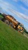
Just bought a 1994 A25 c, black cab. And in the process of tidying up a few bits on her.
So might be on here a bit with a few silly questions:
Im based in ireland.
Can anybody tell me, there is two brake fluid resorvoirs at the back of the cab, i think one of them is for the fore most of the rear axles ? whats the other? front im presuming?

MAchien goes through all the gears nice in manual or auto , but in automatic it seems to change down a bit harsh ? any ideas?

On the brakes side of things ? if there is calipers jammed , are they hard to sort out? any diagram? can u geta re build kit?

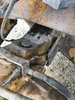
I see the cap is missing of the rear diff actuator? not problem in sorting that but would there be any reason inside a guy would disonnect that? or shoudl i watch for what?

I have an oil leak too on one of the hubs , comes down the inside of wheel ? Presume some seal? what could it be and is it difficult to replace.?

Im looking for the rear underhung tailgate , but proving difficult to find ? anyone know of one? dosnt matter what country.

Thanks again guys

J
 

Attachments

  • volvo1.JPG
    volvo1.JPG
    196.6 KB · Views: 27
  • volvo diff.jpg
    volvo diff.jpg
    91.4 KB · Views: 28
Last edited:

sfrs4

Senior Member
Joined
Jul 22, 2013
Messages
697
Location
Great Britian
Occupation
parts admin
1. Both are for the front axle
2. Try the load sensor attached to the fuel pump
3. Calipers have seal kits and pistons available for them or you can get recon units if your not wanting the work
4. The rear diff cap could be someone had a busted diff and decided to remove the actuation, pop an planetary cap off and see if the half shafts are still in there!
5. Hub seal, not an expensive part BUT check the wear ring it runs on, if that is slightly groved as well it'll need replacing as well, careful as there is a super session in place with the hub seals and you will need to know whether you have original (seal spins on the wear path) or new cassette type (seal spins on itself) you need the wheel off planet carrier and hub assy off to change, not to difficult with the right lifting equipment as the hub is heavy.
6. We did have one but sold a few weeks back, not had another A25C in to break yet, so maybe in the future we might but getting hard to get hold of.
 

john biggins

Member
Joined
Jul 15, 2019
Messages
23
Location
ireland
Hi
Thanks a million for the pointers ? If your breaking stuff whats your company. Im getting a few bits for her.
What oil goes in the transmission?
Where is the sensor for the transmission temp located? couldnt find it.
Where is the rev clock sensor run from, not registering.
Thanks again appreciate help

J
 

sfrs4

Senior Member
Joined
Jul 22, 2013
Messages
697
Location
Great Britian
Occupation
parts admin
Hi
not sure on Forum rules with regards to and i try not to "tout" for business on here, i will send you a private message with regards to the company i work for.
the trans oil we use is ATF Dexron 3
the trans oil sensor is on top of the block that the oil cooler pipes run out of
 

john biggins

Member
Joined
Jul 15, 2019
Messages
23
Location
ireland
Is there as diagram showing what the different hydraulic pumps do? or their purpose
was trying to figure them out last night,
HAs any particular pump more to do with tipping?
or how would i test it.
 

Mark250

Senior Member
Joined
Aug 30, 2015
Messages
1,243
Location
victoria,Australia
Occupation
heavy equipment technician
upload_2019-7-18_20-26-35.png


Hydraulic diagram A25C 6x6
1 Hydraulic pump for steering and dumping systems (R)
2 Hydraulic pumps for steering and dumping systems (L)
3 Hydraulic pump for fan motor (R)
4 Restriction valve for fan motor with pressure check connection for cooling fan pump
4A Solenoid valve for high fan speed
5 Thermostat valve for fan drive
6 Hydraulic motor for fan drive
7 Oil filter for oil from fan motor with non-return valve and by-pass function in filter cartridge
8 Non-return valve block with pressure check connection for ground dependent pump 12, pressure sensor V16
9 Hydraulic cylinders for steering
10 Damping cylinder for steering
11 Hydraulic cylinders for dumping load body
12 Hydraulic pump, ground dependent for steering (L)
14 Non-return valve block with two pressure check connections for hydraulic pumps 1 and 2, pressure sensor V17
15 Oil filter with by-pass function for return oil to tank with filler plug
16 Shut-off valve for hydraulic oil
17 Cross-over valve for oil pressure in lines A and B
18 Cross-over valve for line B, damping cylinder X1 – Y2
19 Cross-over valve for line A, damping cylinder X2 – Y1
20 Shock valve, line A
21 Shock valve, line B
22 Anti-cavitation valve, line A
23 Anti-cavitation valve, line B
24 Restriction valve for signal oil pressure, ground dependent pump 12
25 Restriction valve for signal oil pressure to pumps 1 and 2
26 Cross-over valve for signal oil pressure from dumping and steering to pumps 1, 2 and 12
27 Dumping valve with dump limiting valve (relief valve)
28 Steering valve
29 Non-return valve with back-pressure function 1.2 MPa (12 bar) (174 psi)
30 Non-return valves without back-pressure function
31 Pressure indicators
32 By-pass valves for oil filter
33 Air filter with valves
34 Level switch, V3
35 Restriction
36A Pressure check connection, pump 1
36B Pressure check connection, pump 2
36C Pressure check connection, ground dependent pump
36D Pressure check connection, pump for cooling fan
37 Drain for hydraulic tank
38 Shock/anti-cavitation valve, lowering load body
39 Shock/anti-cavitation valve, dumping load body
40 Signal valve, dumping load body
41 Signal valve, lowering load body
42 Load holding valve
43 Non-return valve with back-pressure function
50 Hydraulic oil tank
(R)=right rotation
(L)=left rotation
 
Top