• Thank you for visiting HeavyEquipmentForums.com! Our objective is to provide industry professionals a place to gather to exchange questions, answers and ideas. We welcome you to register using the "Register" icon at the top of the page. We'd appreciate any help you can offer in spreading the word of our new site. The more members that join, the bigger resource for all to enjoy. Thank you!

Line Boring Systems

RayF

Senior Member
Joined
Jul 8, 2011
Messages
640
Location
Perth Western australia
Occupation
lineborer/welder
You do have a way to adjust the bearing after its been welded right?
Some of my self aligning bearing are a bit tight in the swivel. After the bar is through I will often tap it with a soft hammer. That will make all the bearings self align.
 

ETER

Well-Known Member
Joined
May 31, 2015
Messages
158
Location
Upstate New York
Gotcha W.M. I guess that I should have figured out that one! Yup, tunking the self aligning bearings (the end bearings) does seem to help...not so much on the middle supports. I have to build some adjustables for in the middle as RayF suggests. BuMach, that is a pretty good idea on the Construction Holiday, I can see where it would keep everyone one the same sheet of music.
Regards, Bob
 

StanRUS

Senior Member
Joined
Mar 7, 2016
Messages
767
Location
Cal
You do have a way to adjust the bearing after its been welded right?
Some of my self aligning bearing are a bit tight in the swivel. After the bar is through I will often tap it with a soft hammer. That will make all the bearings self align.
RayF,
NO provision for relieving residual welding stress caused by tacking to support brackets. RayS will be farting around wasting time every time he sets up.

RayS,
I’ve already replied in your thread LINE BORING SYSTEMS that you will have this issue! York’s support bearing design does not offer a simple fix, new parts are required...want assistance PM, not a freebie I won’t give free designs to Dennis Canbrey, York’s owner.
 

Attachments

  • vlcsnap-error157.png
    vlcsnap-error157.png
    299.3 KB · Views: 314

ETER

Well-Known Member
Joined
May 31, 2015
Messages
158
Location
Upstate New York
W.M., Gonna have to see some cool pics at some point here on these bearing supports (not so creative on my own, need to borrow some ideas!). StanRUS, is that the York kit you have pictured above? (too tired to google).
Regards, Bob
 

StanRUS

Senior Member
Joined
Mar 7, 2016
Messages
767
Location
Cal
W.M., Gonna have to see some cool pics at some point here on these bearing supports (not so creative on my own, need to borrow some ideas!). StanRUS, is that the York kit you have pictured above? (too tired to google).
Regards, Bob

Bob,
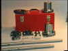
I don't own, use & have never seen a York in person. The photo is from York's promo video, downloaded and using VLC player a photo snap shoot.
U tube link https://youtu.be/qfsUY6UVVgI VCL also can do slow motion and frame-by-frame, viewing the video that way I am less than impressed with the design of the carriage assembly, drive motor to boring bar interface (coupling). All the machines in the video have obvious boring bar run-out (not straight), that causes the carriage to wobble around...impedes bore machining accuracy-surface finish. Line boring IS NOT just about removing XXX amount of material but also how ROUND is the finish bore after the machining operation is finished...Roundness cannot be measured with any 2-point measuring instrument(s) all that gives you is a diametrical measurement across 2-points.

All the machines except (Hofmann or Italian type) that require removal of support bearings to use a stand-alone bore welder require some means to realign the support bearing(s) after bore welding. WM's York; remove the bearing support's 4ea mounting bolts, @ re-install alignment relies on bar-to-bearing fit...any perpendicular bearing support's FACE-to-Bracket face issue can result with a bit of bore axis displacement...

Older Climax Mod1149, NO spherical bearings, directly mounted to the support arms with 4ea 1/2"-NC bolts, 4ea 5/16th" jacking bolts to adjust perpendicular alignment & 4ea 5/16th" jacking bolts to adjust radial displacement (up-down-side-ways); NOT users friendly & very time wasteful...To use the 1149 without the mickey mouse procedure given by Cmax; LOCK spindle to boring bar with the spindle collects onto an ALIGNED BORING BAR, same for opposite support bearing (non adjustable-spherical directly mounted into the support arm) Lock collect to boring bar...push the arm hand tight against the work piece & tack weld @ closest point...if there a gap use metal scrap to bridge (washer, nut, re-bar, small wedges, 7018 welding rod with flux knocked off etc)...after tack welding both support arms...LOOSEN each mounting bolt (& face jack bolts) & retighten individually BEFORE loosening spindle-bearing collects. Loosen collects; bar has to slip back & forth easily!!!! Typically requires less than 15 minutes.

Set-Up Cones, all they do is hold the bar to approximate center-of-bore axis, even Engine line borers' set-up cones & support bridges just hold the bar to approximate bore C/L...for construction equipment I never use them preferring 4 legged adjustable spiders used to align the bar. My buddy uses spiders & aluminum disc.

Cmax, their BB5000 set-up video,' most of the time set-up cones are all you'll need'! Complete BS...

To be continued
 

ETER

Well-Known Member
Joined
May 31, 2015
Messages
158
Location
Upstate New York
Thanks Stan, I did check out the youtuber on that one....W.M. I realize that I am not inventing the wheel here (or even re-inventing), but I have been using two and four bolt self-aligning bearing flanges and once the ends are locked on center, I can leave the middle support bearing flanges loose 'til the bar floats properly the snug the flange mount bolts down then tunk the bar again...this usually seems to have to be repeated. I am still planning on making supports that can be "dialed-in" though.
Don't have any set up cones yet (I can see that they would be handy at times), but have been making bushings for my 1.5" bars as needed.
Regards, Bob
 

StanRUS

Senior Member
Joined
Mar 7, 2016
Messages
767
Location
Cal
Y1.pngY4.png
Thanks Stan, I did check out the youtuber on that one....W.M. I realize that I am not inventing the wheel here (or even re-inventing), but I have been using two and four bolt self-aligning bearing flanges and once the ends are locked on center, I can leave the middle support bearing flanges loose 'til the bar floats properly the snug the flange mount bolts down then tunk the bar again...this usually seems to have to be repeated. I am still planning on making supports that can be "dialed-in" though.
Don't have any set up cones yet (I can see that they would be handy at times), but have been making bushings for my 1.5" bars as needed.
Regards, Bob
Guys, working on the project...York is sending CAD prints for their Head Mount, prevent my wasting a few thous $$$ worth time guessing dimensions etc:confused:
Photo spindle coupling-to-bar, to prevent galling caused by machining dust and make separation easier...cover the coupling area with bike inter tube kept in place with electrician's tap. Coupling is stainless:Banghead, stainless galls very easily

Quick look at CAD file, Head Mount DOES have index; York's rep stated otherwise...their sales reps always goof up example 'we do not have a facing head for 2.25" bars' = wrong.
 
Last edited:

StanRUS

Senior Member
Joined
Mar 7, 2016
Messages
767
Location
Cal
Modern Portable Line Boring 1903 Underwood, modern compared to 1775 Wilkinson - 1st portable line borer.
1903 H. B. Underwood  Co., Portable Clyinder Boring Bar..jpg

1903 H. B. Underwood  Co., Portable Clyinder Boring Bar.jpg

WM,
When you get back from Alaska, post couple photos of your York & DYI mounting plates...York does make a Mounting with 5/8" adjustment & 6deg spherical adjustment.
 
Last edited:

Ivy

New Member
Joined
Jun 27, 2017
Messages
4
Location
Perth WA
You know someone who are legitimate to work in Perth Australia as line borer? im in need now thanks.
 

StanRUS

Senior Member
Joined
Mar 7, 2016
Messages
767
Location
Cal
Hello Ivy,
PM Rayf, Perth is his' turf, he probably knows most of the lineboring mobs.
Question, does Aussie-land have Poison Ivy?
 

BuMach

Well-Known Member
Joined
Jun 7, 2015
Messages
198
Location
The Netherlands
Dean Eccles from Eccles lineboring services ltd is a good well knowledgable bloke around there.

I dont have his nr yet cause i met him on Linkedin but if you want i can ask for it.

Good luck
 

Ivy

New Member
Joined
Jun 27, 2017
Messages
4
Location
Perth WA
Dean Eccles from Eccles lineboring services ltd is a good well knowledgable bloke around there.

I dont have his nr yet cause i met him on Linkedin but if you want i can ask for it.

Good luck
Thanks BuMach i think already connected to him via Linkedin
 

StanRUS

Senior Member
Joined
Mar 7, 2016
Messages
767
Location
Cal
JLM Lineboring & Engineering, Perth
Joepie van der Poll

Borex Pty Ltc, Perth
HR Wendy Pearson
 

Mink

Well-Known Member
Joined
Feb 20, 2016
Messages
73
Location
Alma Canada
Occupation
Machinist
Hello. I am looking to do a job that requires circlip but I do not know how to do with a line borer. I'm not facing head. Has anyone ever done it? Thank you!!
 

StanRUS

Senior Member
Joined
Mar 7, 2016
Messages
767
Location
Cal
Hello. I am looking to do a job that requires circlip but I do not know how to do with a line borer. I'm not facing head. Has anyone ever done it? Thank you!!
Circle Clip = Snap Ring Groove with line boring bar. NO automatic facing head!
1)...if the existing groove is not totally worn out, use copper tubing or wire shaped to fit into the groove before bore welding. When you bore the tubing or wire will machine-peel out.
2)...use HSS tool bit ground for cutting the groove...depth and groove width @ groove cutting end.
3)...to adjust cutting depth requires
A...braze nut to HSS bit to use jack screw by pushing against bar advancing 0.0005" each adjustment. Start allow 20revs, stop, adjust, start allow 20revs...keep going until correct groove depth is achieved. Use heavy cutting oil!
B...Grooving Thingy...make 2-3 identical split rings that clamp onto your boring bar, upper part of split rings with 0.375"-10mm bore. Semi circular grooving tool bit, shaft and threaded jacking arm.
I'll email a cartoon, 6.30.17 with instructions
 
Top