• Thank you for visiting HeavyEquipmentForums.com! Our objective is to provide industry professionals a place to gather to exchange questions, answers and ideas. We welcome you to register using the "Register" icon at the top of the page. We'd appreciate any help you can offer in spreading the word of our new site. The more members that join, the bigger resource for all to enjoy. Thank you!

Volvo EC210C windshield wiper issue

suladas

Senior Member
Joined
Jun 30, 2016
Messages
1,731
Location
Canada
Got some time to try and get this fixed again spent the better part of the day and no luck. I put in the new wiper motor and no change, but oddly I plugged in the old one and fuse no longer blows no matter what? Motor is getting power with key on, but nothing else with either switch activated, ground wire was also fine. The washer switch works fine.
Comparing my controller to the diagram above, mine has 16 pins that one shows only 10? But some of the numbers seem to make sense with what I tested.

What I found with the key on was numbers 1 and 5 have power 8 and 13 light up test light but very dim?
With the switch in int 3 get power
With the switch on 2 and 3 have power
With the switch on int or on I can hear it clicking every once in awhile
I checked continuity between the motor and controller and found something odd, but wires the blue/white and green/yellow have large resistance with nearly every pin on the controller? Blue/white for example has resistance with 3,4,7,8,10,11,12,13,14,15,16?

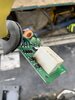
I attached a picture of the controller, definitely a bit of black on it? Am I wrong to assume the controller is likely done and my issue?
 

Attachments

  • IMG_0780.jpg
    IMG_0780.jpg
    1.2 MB · Views: 16

suladas

Senior Member
Joined
Jun 30, 2016
Messages
1,731
Location
Canada
Realized I made an error in testing with the controller plugged in. I re tested with it unplugged, on int 3 has power and on 2 and 3. So the controller is not passing on any current/signal. Only thing I don’t know is, is it because it’s not working, or is it missing power to another pin in order to work?
 

suladas

Senior Member
Joined
Jun 30, 2016
Messages
1,731
Location
Canada
Called the dealer just to see what a controller would cost, $1000! So definitely not buying that unless I’m 100% sure it’s the issue. I would also imagine if it’s the problem could probably have it repaired somewhere for a lot less?
 

suladas

Senior Member
Joined
Jun 30, 2016
Messages
1,731
Location
Canada
Still haven't had any luck trying to track down another diagram. I did find a used controller for sale but i'm still not 100% sure that it's the problem. Anyone have any ideas how I could test to know for sure?
 

uffex

Senior Member
Joined
Jan 23, 2012
Messages
4,464
Location
Lincoln UK
Occupation
Admin
Good day
You may find the attached helpful, I may be able to get an animated version if you need, it only works on the Windows platform.
Kind regards
uffex
 

Attachments

  • Wiper C series.pdf
    909.8 KB · Views: 20

suladas

Senior Member
Joined
Jun 30, 2016
Messages
1,731
Location
Canada
Thanks for the diagram it helps a ton. I’ve never been able to find the upper limit switch SE3602 any idea where it is located?
 

suladas

Senior Member
Joined
Jun 30, 2016
Messages
1,731
Location
Canada
Didn't make any progress, just getting more frustrated with tracking down this stupid problem.

I have searched and searched for how to read the electrical diagram and no matter what it makes no sense. If I assumed the non-colored dots mean the wire is connected, that means every single wire to the controller is connected all 16 of them which isn't possible, if I assume it means they aren't connected it means many wires just dead end which also isn't possible, if I assume that it's a ground I know that's wrong because 2 and 3 on the controller have power with the upper switch on. Can anyone clear up how you're suppose to read that diagram in that regard? Specifically the circle around CU3601 that seemingly connects every single wire of it?

The one thing I am 100% sure on is the controller is not completing any circuits, doesn't matter which wiper switch I have on.

I cannot find out where the upper limit switches are?

What is the best place to buy a manual from? I really want to have access to all these diagrams when I need and not bother others for them.
 

suladas

Senior Member
Joined
Jun 30, 2016
Messages
1,731
Location
Canada
What is the issue that you are having. Is it still blowing fuses or is just not working?

Not working, it no longer blows fuse. There is fused power to wiper motor and good ground but switches don't provide it any power. Wiper sprayer motor works with switch. Controller has good fused power, and is getting power to wires 2 and 3 with switch on. What I am not sure is, is the controller missing another wire to work, or is the controller bad? At $1000 for a new one, or $300 used I don't want to guess wrong.
 

BigWrench55

Senior Member
Joined
Oct 11, 2018
Messages
1,176
Location
Somewhere
Did you check your limit switch?
It is on the front glass on the upper right hand corner. That switch is there so that you can't operate the wipers when the glass is raised.
 

suladas

Senior Member
Joined
Jun 30, 2016
Messages
1,731
Location
Canada
Did you check your limit switch?
It is on the front glass on the upper right hand corner. That switch is there so that you can't operate the wipers when the glass is raised.

Yes i've made sure that is engaged and I can verify it is working because the spray motor won't work otherwise. That's called the limit switch?
 

BigWrench55

Senior Member
Joined
Oct 11, 2018
Messages
1,176
Location
Somewhere
If you look at the diagram that uffex provided. That limit switch is providing ground to the wiper motor pin-3. Pin-1 is fused power and pin-2 and 5 are from the controller. That controller is a relay of sorts. I believe that it is a solid state relay rather than your conventional type relay. I don't have a lot of experience on these machines but Fun with fuel does. Hopefully he come along and make better sense of this.
 

suladas

Senior Member
Joined
Jun 30, 2016
Messages
1,731
Location
Canada
If you look at the diagram that uffex provided. That limit switch is providing ground to the wiper motor pin-3. Pin-1 is fused power and pin-2 and 5 are from the controller. That controller is a relay of sorts. I believe that it is a solid state relay rather than your conventional type relay. I don't have a lot of experience on these machines but Fun with fuel does. Hopefully he come along and make better sense of this.

Thanks that makes sense. I was looking at it wrong, I thought that box around CU3601 was connecting them but in reality it's just the wires going into/out of the controller so that makes a lot more sense. I ran a jumper to the fused power for it but I didn't try a jumper to a ground to check that the controller is grounded. But unless i'm missing something it has power to pins 2 and 3 as it should with the switch on, other then the ground being bad the controller should be sending power to that motor through 9 and 11, unless the controller is bad?
 

BigWrench55

Senior Member
Joined
Oct 11, 2018
Messages
1,176
Location
Somewhere
Yes. The pin numbers I stated earlier are at the wiper motor. Pin-9 from the controller goes to pin-2 at the wiper motor. Pin-11 from the controller goes to pin-5 at the wiper motor. I am assuming those are the high and low signals. I have only been working on these volvos for 2 years and I have yet to make any sense of their schematics. I don't believe that Volvo provides a real schematic. They give you little diagrams like you see above. I personally want to see the machines wiring in all its glory rather than bits and pieces.
 

funwithfuel

Senior Member
Joined
Mar 7, 2017
Messages
5,575
Location
Will county Illinois
Occupation
Mechanic
looking at schematic, fused power coming in at pin 1 is return to park. That's all it's for. Pulse coming from CU3601 at pin 5 controls motor. That way if you shut the wiper off in the middle of the stroke, it can finish it's cycle and return to park independent of the switch. The motor only runs at one speed, it's the pulse from CUC3601 which dictates delay or the illusion of speed. As Paul had mentioned, the ground is completed via SE3602
I believe you stated earlier that you caused the motor to run by applying voltage to pin 5, proving the motor works. So, my suggestion is, measure voltage at pins 2 & 3 while switching switch from off to delay to on. This is verifying that the switch signal is reaching CU3601. Then please measure voltage at pin 11 of CU3601. If each has voltage as the switch position changes, you're good. Remember, the CU is the timer delay. The relay is shown to illustrate how power is transferred. You have to be measuring voltage while switching or you won't catch it. It's a pulse, not an on/off switch. It just gets the motor turning. It doesn't handle the load. Hope this helps
 
Last edited:

BigWrench55

Senior Member
Joined
Oct 11, 2018
Messages
1,176
Location
Somewhere
Thanks for clearing that up. I just haven't been working on these long enough to know all of the idiosyncrasies of these machines. Plus this is a older model and I work on those even less. Most of what is in my market is new.
 
Top