• Thank you for visiting HeavyEquipmentForums.com! Our objective is to provide industry professionals a place to gather to exchange questions, answers and ideas. We welcome you to register using the "Register" icon at the top of the page. We'd appreciate any help you can offer in spreading the word of our new site. The more members that join, the bigger resource for all to enjoy. Thank you!

Circuit Boards

John C.

Senior Member
Joined
Jun 11, 2007
Messages
12,870
Location
Northwest
Occupation
Machinery & Equipment Appraiser
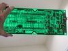
That confirms what I was told. When I studied the traces I see that in the non-energized condition there are no connections to anything. When energized two circuits on each side are connected. When I power up the board the relay is energized and an alarm is going sounding. Since I could only get a relay to cover the one side I just joined the other side with copper wires so that they were on all the time. I'm guessing now that relay is some sort of inhibit as the wire side traces got down to an IC. When I'm up there again I'm going to cut the wires to sever the connection to that IC and see what happens. I'm thinking the worst that could happen is the alarm shuts off. I'll post what I find.

Thanks again!
 

John C.

Senior Member
Joined
Jun 11, 2007
Messages
12,870
Location
Northwest
Occupation
Machinery & Equipment Appraiser
When I was up there yesterday I took some photos of the machine to maybe help people understand the issues. It doesn't just drill a hole in the rocks. There is a wedge device that can rotate into the position of the drifter and be moved into the hole. There is a wedge in between to pieces of steel that is pushed down forcing the steel halves apart hopefully splitting the rock.

IMG_5064.jpg

IMG_5071.jpg

IMG_5072.jpg
 

John C.

Senior Member
Joined
Jun 11, 2007
Messages
12,870
Location
Northwest
Occupation
Machinery & Equipment Appraiser
Here is the wiring in the control panel that hooks up to the circuit boards.

IMG_5067.jpg

And here is the control panel.

IMG_5066.jpg

The compressor and dust collection systems are installed where the counterweight would be.

IMG_5070.jpg
 

John C.

Senior Member
Joined
Jun 11, 2007
Messages
12,870
Location
Northwest
Occupation
Machinery & Equipment Appraiser
This machine has an extra pump installed that I have never seen done on a Komatsu before.

IMG_5069.jpg

There is an extra set of control solenoids mounted on the drill mast.

IMG_5065.jpg

It all runs off those two integrated circuit panels.
 

John C.

Senior Member
Joined
Jun 11, 2007
Messages
12,870
Location
Northwest
Occupation
Machinery & Equipment Appraiser
I cut out the wires that I put in to take the place of that big relay and I got all the systems working in manual mode now. I suspect something is amiss either in one of the three ICs or I have a bad wire somewhere. The LED #4 stays on all the time and I can't get the air solenoids up on the mast to open up. There is a cannon plug on the machine txt the retaining ring is stuck on and I can't get it to unscrew so I can check the connections. I'll bring some bigger tools to loosen it next time I'm up there. I did remove the boards again, hopefully for the last time to take some photos with a light behind to show the traces. These are a little bigger fines for more detail. The first is the bottom board basically looking down on it.

IMG_5077.jpg
 

Attachments

  • IMG_5078.jpg
    IMG_5078.jpg
    471.3 KB · Views: 0
  • Like
Reactions: mks

John C.

Senior Member
Joined
Jun 11, 2007
Messages
12,870
Location
Northwest
Occupation
Machinery & Equipment Appraiser
Here is the top board doing the same thing plus turned over.

IMG_5079.jpg IMG_5080.jpg
 
  • Like
Reactions: mks

John C.

Senior Member
Joined
Jun 11, 2007
Messages
12,870
Location
Northwest
Occupation
Machinery & Equipment Appraiser
Well I got the machine to work yesterday and am finally working on the peripheral stuff to make it operational.

I found out how the boards work and what is wrong in the electrical system. Somewhere in the harnesses between the cab and the mast there is a short circuit in the wiring that opens the air valves to allow air from the compressor to go through the hammer and out the drill steel. I checked the circuit from the board out to the solenoid and the wire was good. I checked between the hot and the ground wire and they had no continuity. I hooked up and jumper at the solenoid and it opened with no problem. Next, I hot wired the circuit at the outlet of the board and then things got hot fast. The builders put this system together with 20 gauge aluminum wire and the insulation got hot enough to bubble as soon as I energized the circuit. I killed the power before the fuse blew and more damage was done to the boards. The hot wire going to the air solenoid was grounded somewhere. When I traced the ground wire back through the harness plugs I found the ground wire was melted out of the pin just before going into the boards. The fix was to run another set of wires to that air solenoid outside of the circuit boards and put in a new switch to run it. It appears the big relay that I took out of the system was the failsafe and was keeping the system shut down while the fault existed. At any rate the automatic compressor function no longer works but there is a switch that allows the compressor to be run manually. All the rest of the safety stuff works along with all the rest of the drill functions.

We installed a steel on the hammer yesterday and tried drilling a hole in a rock. There is some adjusting to do but it did work. I installed the dust collector hoses today and should be ready to try it out again tomorrow. I'll get some video of the thing working if the rain isn't coming down real hard.
 
Top