• Thank you for visiting HeavyEquipmentForums.com! Our objective is to provide industry professionals a place to gather to exchange questions, answers and ideas. We welcome you to register using the "Register" icon at the top of the page. We'd appreciate any help you can offer in spreading the word of our new site. The more members that join, the bigger resource for all to enjoy. Thank you!

MF 50a alternator replacment and wiring guidelines

steven mf50A

Member
Joined
Aug 28, 2020
Messages
11
Location
Saint-lin-laurentides
Hello Everyone
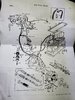
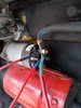
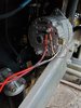
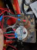
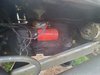
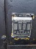
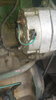
I recently bought a old tractor loader MF50a it dosnt have the back hoe on it. I am having some issues with wiring. I replaced the alternator on it since it was making noise and noticed that the amp meter wasnt working either. So i looked at the original wiring for the tractor but its for the old system with a generator and a voltage regulator. My alternator is the AC delco with the built in regulator and I just cant seem to understand how to wire it. I need some help please. It seems like the wiring was modified after all the years but done not correctly.
Thanks
 

Attachments

  • 2020-09-28 09.12.49.jpg
    2020-09-28 09.12.49.jpg
    1.9 MB · Views: 22
  • 2020-08-19 06.34.35.jpg
    2020-08-19 06.34.35.jpg
    3.5 MB · Views: 24
  • 2020-08-18 07.57.07.jpg
    2020-08-18 07.57.07.jpg
    2.5 MB · Views: 21

Delmer

Senior Member
Joined
Jan 3, 2013
Messages
8,887
Location
WI
I would bypass the amp meter, or replace it with a volt meter, an amp meter is appropriate for a generator, a voltmeter is good enough for an alternator, or even just an idiot light is fine too.

Your big wire should go from the hot terminal on the solenoid directly to the alternator big nut terminal B+, one of the small spade terminals goes to the ignition switch, and the other one can be hooked directly to the big nut terminal B+ on a tractor with virtually no electrical demand.

Look up the wiring diagrams for the alternator, it's simple if you can find the original generator regulator wire that is switched from the ignition switch. You CAN run the alternator off the Ammeter, but it's not worth it to me, it will do fine for a simple tractor if you want it to stay more original.
 

Tinkerer

Senior Member
Joined
May 21, 2009
Messages
9,367
Location
The shore of the illinois river USA
Steven ;
Can you post a better picture of your wires on the alternator ?
We need to see how they are connected to the alternator.
If you read that thread I posted the link to, you find that those alternators can be wired in different configurations.
 

Delmer

Senior Member
Joined
Jan 3, 2013
Messages
8,887
Location
WI
So John Hofer probably already took the nut and the big wire off that terminal. That shows the simplest way to hook up a delco alternator.

IF yours is a one wire alternator, then you don't need the two small spade terminals hooked up to anything.
 

steven mf50A

Member
Joined
Aug 28, 2020
Messages
11
Location
Saint-lin-laurentides
So thanks guys gor the answer very appricate it. I went to the massey dealer the other day and they also provided some.help but its still not clear for me. They gave me these wiring diagrams and said this should help. Now i am just more confused. I removed the voltage regulator since they told me.it should be intergrated in the alternator.16033224311577796471035795394107.jpg 16033224575216727620801358235218.jpg 16033224820388746945238624885629.jpg
 

steven mf50A

Member
Joined
Aug 28, 2020
Messages
11
Location
Saint-lin-laurentides
Thanks it seems to be like the wiring diagram the tractor dealer gave me. But my alternator they told me should have a built in regulator in it.
 

Attachments

  • 1603322633478955419147381525458.jpg
    1603322633478955419147381525458.jpg
    2.1 MB · Views: 4

edgephoto

Senior Member
Joined
Aug 13, 2019
Messages
732
Location
Stafford, CT
The wiring diagram for you machine shows an externally regulated alternator. You bought a GM replacement alternator that is internally regulated.

Do you want an ammeter? if not the wiring is much simpler. I would wire an idiot light and no ammeter if I were in your shoes. This is very simple to make it charge. Rewiring some things to get them working correctly will need to be done according to the way the original system is wired.
 

Delmer

Senior Member
Joined
Jan 3, 2013
Messages
8,887
Location
WI
the simplest way to make it work is to hook it up like John Hoffer's pic, which is the same as your first pic, you don't need a diode because you have a diesel, right?

Even simpler, run the big wire directly to the starter solenoid battery connection, bypassing the ammeter.

If you have a pressure gauge instead of an ignition switch, you'll have to have it running to see what is switched by the pressure switch to give you a hot for the alternator feed. Or short across the switch to see what wire to use for your feed. This is for the spade terminal that is not hooked to the big threaded terminal.
 

john hofer

Well-Known Member
Joined
Nov 24, 2014
Messages
116
Location
alberta, canada
I think the confusion comes from the generator and the alternator. You have the drawings for both, you need to decide which one you want to use.
The generator needs a voltage regulator.
The alternator does not. The simplest to make work is the GM alternator.
 

Tinkerer

Senior Member
Joined
May 21, 2009
Messages
9,367
Location
The shore of the illinois river USA
Umm,
Did you connect the wires onto the replacement alternator the same way they were on the old one that was making noise ?
This is why I was hoping you would post a picture of the new alternator and the connections on it.
 

edgephoto

Senior Member
Joined
Aug 13, 2019
Messages
732
Location
Stafford, CT
Looks like his original setup had an alternator, not a generator, that was externally regulated. Some wiring changes will need to be made to accommodate the GM alternator.
 

steven mf50A

Member
Joined
Aug 28, 2020
Messages
11
Location
Saint-lin-laurentides
So I got around to starting the wiring. It seems like the volt meter dosnt light up only when I start it its getting voltage. So I installed the new pressure switch but not sure which connecting terminal the wiring goes to. One says nc and the other is c . Here are some pictures. I installed the diaode like it says towards the alternator on the #1 terminal. So if you have any ideas please let me know. Thanks again for all the posts guys. 20201024_171450.jpg 20201024_171450.jpg
 

Attachments

  • 20201024_171414.jpg
    20201024_171414.jpg
    1.4 MB · Views: 8
  • 20201024_171418.jpg
    20201024_171418.jpg
    1.6 MB · Views: 8

Delmer

Senior Member
Joined
Jan 3, 2013
Messages
8,887
Location
WI
the alternator looks good, the starter looks good, I can't see what's between them, or the rest of the connections, you'll have to compare to the wiring diagrams, or show all the connections and label the wires to get any more specific advice. Do you have a key switch? or just a start push switch?

The pressure switch, if it has three terminals, they'll be NC/normally closed, C/common, and NO/normally open, right? Don't use the NC terminal, use the other two to turn on your alternator and volt meter when the oil pressure rises, and off normally, that is when there is no pressure.

Unless your voltmeter comes on with the engine off, and then doesn't work when running, then their definition of normal is different than mine.
 

steven mf50A

Member
Joined
Aug 28, 2020
Messages
11
Location
Saint-lin-laurentides
So the pressure switch has only 2x connections on the back of it 1- NC 2- C . As for the volt meter it turns on when I am turing the key to start it its a 1/4 turn then it returns back to its position.
 

Attachments

  • 20201024_171500.jpg
    20201024_171500.jpg
    1.7 MB · Views: 5

Vetech63

Senior Member
Joined
Aug 10, 2016
Messages
6,412
Location
Oklahoma
I believe you are making this harder than it needs to be. A voltmeter only needs to see a system ground on 1 side and system positive voltage on the other side. Ground the negative terminal of the voltmeter, the connect the positive from the voltmeter to the ignition side of your ignition switch. This way you will only show voltage when the ignition is on. If you read voltage on your meter when the key is off, then you have the positive side of the meter hooked into the supply side of your battery power which will run your battery dead when sitting over a period of time.

What is the pressure switch for?
 
Top