hammerdwn20
Well-Known Member
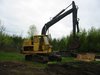
The position of the plunger definitely doesn't look right. It looks engaged & the linkage is on too much of an angle for the clevis or turnbuckle to be mounted that way.
Unless it has very short travel, but that doesn't make sense, flow wise.
Is there a cap at the back end of the valve body, on the plunger (this is where the spring/self centering is), like the other plungers?
This is the one that is sticking?
Are the hyd. lines that come out of it the ones with the quick connects on them at their ends?
Looks like they tapped into the dipper & right track motor hyd. circuit for the auxiliary hyd. circuit?
The hyd. oil flow from the dipper circuit pump will be twice that of the swing circuit.
There will be an O ring & a wiper (sometimes just a Quad ring) inside the bore of the valve body positioned at either end of the plunger. If the plunger goes too far it can stick there.
If the linkage is too angled (it will likely stick), the clevis should be turned (with the plunger) so it is 90 degrees from where it is shown, or the linkage bent so it's straight (in line) to the bore.
Could be set up for a hammer, but that would reduce the flow to the dipper & you need to use that when you're running the hammer.
If I get home soon enough tomorrow, I'll look at the manual for that machine & see if I can find anything.
That spool has a very short travel. No cap on the back of the spool. Can see the spool move on the backside also. Looking at the plumbing it goes out to the one quick connect and then the other quick connect is T'd Into the return line i believe. It does not appear to be a bidirectional circuit and Could have been set up for a hammer. Machine has a 2ft rock bucket and i believe the previous own said it was used to dig test pits for some kind of engineering company.