• Thank you for visiting HeavyEquipmentForums.com! Our objective is to provide industry professionals a place to gather to exchange questions, answers and ideas. We welcome you to register using the "Register" icon at the top of the page. We'd appreciate any help you can offer in spreading the word of our new site. The more members that join, the bigger resource for all to enjoy. Thank you!

Massey Ferguson 50H Stabilizer Removal

Jim Kennedy

Member
Joined
Jul 13, 2015
Messages
24
Location
Australia
I am hoping someone can advise me on removing the stabilizing foot from the end of the piston rod. As can be seen from the pictures there appears to be a plug, maybe screwed in but I cannot turn it.
I don't have a manual yet to see how it goes together. Any help would be appreciated.

Jim
 

Attachments

  • P8060033.jpg
    P8060033.jpg
    191.2 KB · Views: 366
  • P8060034.jpg
    P8060034.jpg
    220.6 KB · Views: 327
  • P8060035.jpg
    P8060035.jpg
    233.6 KB · Views: 454

hookedondiesel

Senior Member
Joined
Jan 24, 2013
Messages
503
Location
Sault Ste Marie Ont. Case 1835C
That does appear to be a nut for sure. Looks like its rusted in there pretty good too.
If it were me, I would use a small grinder, maybe the dremel type and grind around the rusted area flatly, ( not into the area) then apply wd40 etc, heat around the nut, not the nut itself and then try and remove it.
 

Delmer

Senior Member
Joined
Jan 3, 2013
Messages
8,887
Location
WI
I'd scrape the rust out of the hole, use a torch with a neutral-carburizing/rich flame and heat that plug red hot, give it one good tap, and let it cool completely. It should shrink enough to turn right out at that point.

I don't have the right manual, our outriggers are American style. MF would sometimes run a hydraulic line through the rod, but this doesn't look like a spot for a hydraulic fitting at all.
 

Jim Kennedy

Member
Joined
Jul 13, 2015
Messages
24
Location
Australia
Thank you hookedondiesal and Delmer for your helpful comments.
The picture of what seemed to be a screw in plug is just a machined recess that probably had something square forced into the hole. I drilled right through and removed what would have been a pin , maybe it was welded on each side, the
piston rod pin was a good fit in the piston rod end and that was seized. I then heated the rod end and used this puller, and it did a good job. Now I have to remove the other cylinder pin which has been pounded, probably with a large
hammer and swelled the pin and driven in hard.

Jim
 

Attachments

  • P8100001.jpg
    P8100001.jpg
    123.8 KB · Views: 246
  • P8100003.jpg
    P8100003.jpg
    186 KB · Views: 256
  • P8100004.jpg
    P8100004.jpg
    140 KB · Views: 242
  • P8100008.jpg
    P8100008.jpg
    211.9 KB · Views: 234

Delmer

Senior Member
Joined
Jan 3, 2013
Messages
8,887
Location
WI
Thanks for the update. Boy was I wrong, at least I didn't say to weld up the hole and then try to get it out.

Could that have been the round pin hole that had a square punch pressed into to raise some burrs to keep that pin in place?
 

Jim Kennedy

Member
Joined
Jul 13, 2015
Messages
24
Location
Australia
Hi Bowen, Yes the bottom part is meant to stay stationery as the screwed spindle turns. Here are some pictures of the pair of pullers. One for inside and one for outside. The brand name is Licthfield, and old Australian company, not sure if they still exist but they used to make automotive tools of very good quality.
These pullers use a inch and one eight diameter screw with a U.N.F. 12 tpi thread and has 8 inches of travel, they can grip something 12 inches in diameter and has a 5/8 inch barring hole for turning.

Jim
 

Attachments

  • P8190001.jpg
    P8190001.jpg
    217.9 KB · Views: 186
  • P8190004.jpg
    P8190004.jpg
    173.5 KB · Views: 182
  • P8190006.jpg
    P8190006.jpg
    209.9 KB · Views: 186

gtermini

Well-Known Member
Joined
May 29, 2015
Messages
198
Location
Amity, OR
Those are a damn nice pair of pullers. I must own one! Now the ebay hunt begins...

Greyson
 

Jim Kennedy

Member
Joined
Jul 13, 2015
Messages
24
Location
Australia
Hi, I am wondering if anybody can tell me what the three bolts down the outside of the fixed part of the stabilizer on each side. I am still trying to obtain the service manuals and parts manual.

Jim
 

Attachments

  • P9040033.jpg
    P9040033.jpg
    162.6 KB · Views: 160
  • P9040034.jpg
    P9040034.jpg
    176.9 KB · Views: 154
  • P9040035.jpg
    P9040035.jpg
    194.6 KB · Views: 165

AussieChris

Well-Known Member
Joined
Jul 9, 2009
Messages
99
Location
Brisbane, Oz
I don't think they are for wear pads (but I could be wrong). If they were, they would have lock nuts to enable them to be adjusted. If the 50H is like my 50HX it will have a welded-in cage at the bottom of the towers which holds eight rectangular nylon blocks which are replaced when worn. Likewise the sliding inner square tube will have eight pads secured by plates that are welded on.

Also Jim, if your stab cylinders have the same weird gland nuts (wired in rather than threaded) as the 50HX you might like to view this thread https://www.heavyequipmentforums.com/showthread.php?15970-MF-50HX-stabilizer-cylinders&highlight= on how they come apart. I can also help with how to recover them if the wire is broken.

Chris.
 

Jim Kennedy

Member
Joined
Jul 13, 2015
Messages
24
Location
Australia
Hi Chris,
I don't think the 3 bolts on each side are for adjustment of wear, but I don't know what they are for. I think the 50H and the 50HX would probably use the same stablizer legs. There are wear blocks in weld-on cages at the top of the sliding inner square tube but there is nothing like that at the bottom of the fixed towers. My problem was with the bottom of the sliding tube so I re-made the bottom end. My cylinders do have that wire type clip but that did not create a problem. Anyway, it's all back together now and all is good.

Jim
 

Attachments

  • P9040032.jpg
    P9040032.jpg
    210.5 KB · Views: 117
  • P9060001.jpg
    P9060001.jpg
    166.5 KB · Views: 110
  • P9060004.jpg
    P9060004.jpg
    185.8 KB · Views: 112
  • P9060011_2.jpg
    P9060011_2.jpg
    167.2 KB · Views: 121
  • P9100027.jpg
    P9100027.jpg
    177.8 KB · Views: 115

AussieChris

Well-Known Member
Joined
Jul 9, 2009
Messages
99
Location
Brisbane, Oz
Hi Jim,

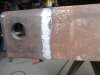
I have to say that's a real nice repair job on the inner legs and way better than how the machine came out of the factory.

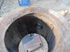
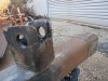
Are your legs still loose at the bottom? On my machine (which had a hard life before I got it), one of the lower cages was completely missing and the other was almost worn through. I know you have it back together now but for reference, the part number for that cage (retainer) is 3501681M92. The top cages (which you have) are 3501693M2. The wear pads are available in differing thicknesses. I can supply part numbers but I remember they were pretty expensive (you need a total of 32 pads) so I made my own out of industrial nylon.

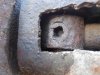
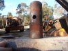
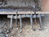
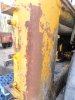
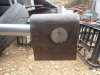
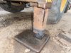
Also, I think I can clear up the mystery surrounding those threaded studs and it's pretty boring. They are simply mounts for the rear road lights (tail lights). While my 50HXS only has two studs on each side you can see how they work in this poor quality photo (and I know, my tail lights are not in perfect condition).
50HXrearlight.jpg
My parts book suggests sometimes the mounts go the other way up so the lights can be either high or low mount (maybe for different countries) so may be that's why yours has three studs.

Again, congrats on the nice repair job.

Chris.
 

mickos

Member
Joined
Sep 27, 2021
Messages
5
Location
Australia
Does anyone know the difference between the MF 50H and Mf 50HX? I have spent a lot of time researching to no avail.
Thanks
 

Jim Kennedy

Member
Joined
Jul 13, 2015
Messages
24
Location
Australia
Scan_20211001.jpg

Hi Mickos,
Here is a page out of the operators manual about the difference in the engines. If you want a copy of this manual just let me know your email.

Jim
 

Attachments

  • Scan_20211001.jpg
    Scan_20211001.jpg
    1.4 MB · Views: 6
Top