dbris
Active Member
Good idea since I wanted to thank you publicly. This is a great group and I'm sure I'll have some more questions.

Good idea since I wanted to thank you publicly. This is a great group and I'm sure I'll have some more questions.
")
I can see I need to put top priority on getting this manual copied and sent out to you guys.
Hey OFF, I wonder if you were to take it to a print shop, would they say "this is copyright material". Then you could say, "well, the copyright must be expired...because this material is no longer available from the people who produced it and obtained the copyright in the first place!" LoL
That's what I'm worried about. I don't want JLG's lawyers to come knocking on my door one day.
Thanks Off, I think you're right that the lump on the end contains the dump valve but I believe that it works differently than the other valves. The dump valve seems to be integral to the valve stack and when any of the proportional valves are activated by their solenoid, the dump valve does it's thing. It does not have it's own solenoid, it's actuated internally. I'd be happy to help out with $$ if we could get access to that manual!


LoL, that's what I'm wondering. Can they come after you for something they don't even have available nowdays? Curious eh?
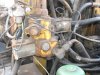
Here's the same lump
View attachment 60653
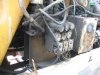
And here's what the back of the lump looks like.
View attachment 60654
I'm 99.99% sure it would have had a solenoid hooked to it just like your other dump valves. Any big hunks of tape hanging around that look like a solenoid by-passed?