• Thank you for visiting HeavyEquipmentForums.com! Our objective is to provide industry professionals a place to gather to exchange questions, answers and ideas. We welcome you to register using the "Register" icon at the top of the page. We'd appreciate any help you can offer in spreading the word of our new site. The more members that join, the bigger resource for all to enjoy. Thank you!

Cat 299D2 Cranks, Won't start

david_

Active Member
Joined
Jun 3, 2021
Messages
38
Location
98125
Ok understand.

When I found the sludge in the fuel filter canister I did drain and attempt to flush out the fuel tank, but it probably wasn't very effective. This is why I believe the actual fuel level to be about 3/4 because of what I put back (after filtering), rather than almost empty as it displays. I'll try and pull the sender today.

I'll pull the rail and polish the overpressure seat better this weekend. The overpressure solenoid is not a separate part you can order from the fuel rail, understandably because of the seat in the rail. But still the rail is $1,400. I'm trying to not think about how much the HPFP would cost. More than the machine is worth?

Luckily I did pull a PSR before I cleared the codes. Attached.
 

Attachments

  • PSRPT1_2022-05-07_14.19.41.pdf
    198 KB · Views: 4

Nige

Senior Member
Joined
Jun 22, 2011
Messages
29,377
Location
G..G..G..Granville.........!! Fetch your cloth.
When I found the sludge in the fuel filter canister I did drain and attempt to flush out the fuel tank, but it probably wasn't very effective. This is why I believe the actual fuel level to be about 3/4 because of what I put back (after filtering),
I don't think that was necessarily a good move. The old fuel should really have been used for another purpose and replaced with new fuel IMHO.
 

david_

Active Member
Joined
Jun 3, 2021
Messages
38
Location
98125
You're right.

Have the sending unit out and there doesn't seem to be sludge. It moves freely. I was mistaken about the fuel level, it is almost empty. It was months ago so I guess I took the old fuel to recycling.

I'm in the process of removing the fuel rail to better polish the seat.
 

david_

Active Member
Joined
Jun 3, 2021
Messages
38
Location
98125
Oh, for the second polishing of the fuel rail, it's not looking so good.

After much work with the fine grit it went from being 'grindy' to absolutely smooth. I thought I was hot sh*t. Then I had a look at it cleaned:
pl2kWy0.jpeg


This was the clearest shot I could get but it definitely did not look 'polished'. I got out my high-mag Coils and there are clearly striations around the seat. Checking the bronze plug, same thing.

So assuming the seat is brass, which it looks like, then it will be softer than the bronze plug, which evidently had the striations from the course grit.

It is definitely improved from before but only a fraction of the surface will be in contact with the solenoid plate. Maybe I should ask the machine shop to re-mill the plug. I don't understand why they wouldn't take a mil or so off the seat; maybe I shouldn't have told them how much the part costs. DOH!
 
Last edited:

david_

Active Member
Joined
Jun 3, 2021
Messages
38
Location
98125
Whelp, I had my bronze tool refaced and ground the seat as best I could. But fuel rail pressure is much worse. In retrospect this should have been a steel tool to match the steel seat. (Threads are recessed away from the hole)

irSxNC7.jpeg


NhVdqDu.jpeg


Y5wfs63.jpeg


NyUbhbY.jpeg


lzCwfkc.jpeg


Since nothing else has changed I suspect it is my wonderful lapping job. I have to buy a new rail now. Although, when reinstalling the rail I left off the feed from the HPFP and cranked it to flush the line. I expected a firehose... but it only piddled.

For red fuel I've found the local CFN distributor (Nelson Petro) and have applied for a card there. Obviously 76 is bad news. And, saving 75 cents/gallon isn't so bad when 5 gallons cost $27. (!)
 

Attachments

  • PSRPT3_2022-05-21_16.30.42.pdf
    176.2 KB · Views: 1
Last edited:

david_

Active Member
Joined
Jun 3, 2021
Messages
38
Location
98125
I'm trying to avoid the idea of a new HPFP. It has got to be preposterously expensive.

I am planning to take it apart to see whether something has gummed it up. Remember the failure happened suddenly when I went down a bump, not gradually over time. I haven't checked yet whether individual parts inside the HPFP are orderable yet. But the advice on keeping its timing is well taken; I don't understand it yet but will when I read the procedure.
 

Mbar

Senior Member
Joined
Dec 15, 2018
Messages
263
Location
North Carolina
Just remember there is always a last time for something to work. Every time I change a starter it creates a argument. I get the saying “I mean it was working fine or “ it hasn’t been acting up “. You can check with Carolina Powertrain in Charlotte. Darrel York is who you need to talk to. I think your motor is kubota if im not mistaken.
 

Nige

Senior Member
Joined
Jun 22, 2011
Messages
29,377
Location
G..G..G..Granville.........!! Fetch your cloth.
I'm trying to avoid the idea of a new HPFP. It has got to be preposterously expensive.
And how much are you prepared on spend on other stuff that is 99% certain not to fix the problem rather than to shell out for a new "preposterously expensive" HPFP.? See post #15 on Page 1.

There are no serviceable parts in the HP pump, neither is a Reman option available.
 

david_

Active Member
Joined
Jun 3, 2021
Messages
38
Location
98125
This doesn't make sense. To find TDC for cylinder 4, "Remove the cover on the flywheel for the Top Dead Center (TDC) mark. Rotate the flywheel counterclockwise and align TDC mark (3) with the TDC mark on the flywheel (2)". I don't see a cover on the flywheel other than the main big cover.

And how can there be only one TDC? Isn't this a four-stroke so that the correct TDC is every other revolution?

And what if I'd removed the idler gear? It doesn't say how that should be set, for the flywheel and pump.
 

Nige

Senior Member
Joined
Jun 22, 2011
Messages
29,377
Location
G..G..G..Granville.........!! Fetch your cloth.
And how can there be only one TDC? Isn't this a four-stroke so that the correct TDC is every other revolution?
The instructions state that you are finding TDC on one particular cylinder, not the other three. In actual fact you are finding TDC on #1 & #4 because on a 4-cylinder engine both those pistons rise & fall together.

According to the instructions the Cover (1) is what they are referring to. Inside it you should find an arrow mark (2) and as you turn the flywheel the TDC mark (3) will appear. Line them up and off you go.

upload_2022-5-27_17-25-4.pngupload_2022-5-27_17-26-51.png
 

david_

Active Member
Joined
Jun 3, 2021
Messages
38
Location
98125
Understand but I've read those instructions over and over and there is no 1TC mark on the big gear visible when the pump cover is off. That big gear is an idler off the crank gear, and it drives the pump idler and cam gear. Is that the flywheel?

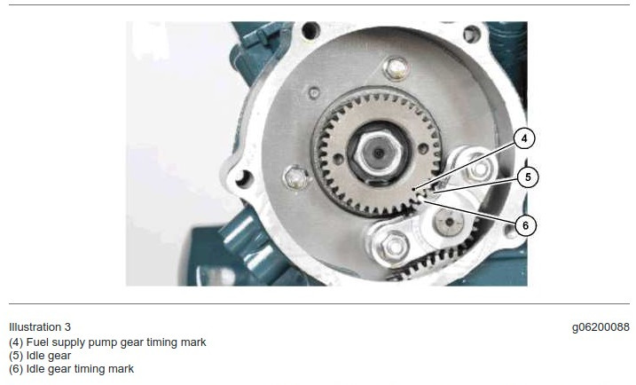
My pump gear and idler look like this:
NtBLw4G.jpeg


I removed its idler gear assembly and turned the crank CCW over and over but no such markings on the big idler gear. And there is no other cover on the front engine cover which might expose this symbol.

On the big idler there is one white marking which annotates two teeth, and another which annotates one tooth. I put an extra mark on one with a Sharpie but that went away when it got dipped in oil as I turned the crank.

Good to know that 1 & 4 compress at the same time, and there are definite points while turning which compress. But it's a 50-50 chance of being 1-4 or 2-3, seems like.

Seems like TDC ought to be annotated on the crank gear, not the big idler, but there doesn't seem to be a way to get at that other than pulling the whole front of the engine. It is a Kubota.

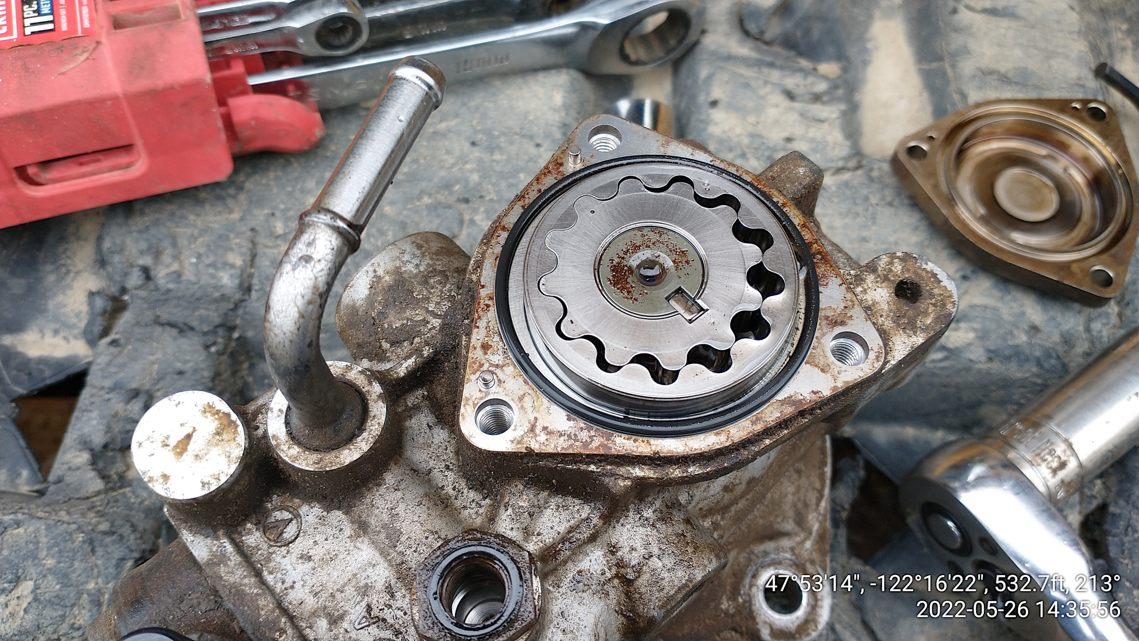
I took apart the HPFP but there sure wasn't much to take apart. I blew out all I could with brake parts cleaner and put it back together. I'd like to try it before I shell out $2,600 for another pump. Here's what the pre-pump gear looks like, quite good:

RtgOWL8.jpeg


I have to suspect that the problem must be in its pressure regulator, but I took it apart as far as I could figure out and never found it.
 

david_

Active Member
Joined
Jun 3, 2021
Messages
38
Location
98125
Understand that. But this presumes that the pump idler is aligned to the big idler. I'd removed my pump idler trying to find the infernal TDC marks.

I could rotate the crank all day long and make the pump idler line up with the pump gear. But the big idler and crank gear must also be at TDC, and that is the problem. Am I being thick?

So it seems to me that:

a. First the crank must be at TDC for cyl 4, but I have found no apparent way to determine that. Fortunately the big idler is still aligned/timed with the crank gear.

b. The pump idler must then be coordinated with the big idler, but the instructions assume that it has already been aligned to the big idler. They give no procedure for setting the pump idler to the big idler, which evidently it must be as it has a mark. Mine is no longer aligned/timed since I'd foolishly removed the pump idler.

c. THEN, and only then, can I turn the pump gear and make it mesh with the pump idler so that the marks match.

Maybe it's because I have a doctorate and come from the computer world, that it looks to me like there are large gaps in the information. For something this important, detail matters.

Unless I am completely misapprehending the situation somehow.
 

Nige

Senior Member
Joined
Jun 22, 2011
Messages
29,377
Location
G..G..G..Granville.........!! Fetch your cloth.
TBH the opinion of the HEF massive is that, unlike a "conventional" (inline or rotary) fuel injection pump, the HPFP on a common-rail engine does NOT need to be timed in order to ensure accurate fuel injection. The reason for this is that the pump supplies a constant flow of HP fuel to the rail, the injection of which into each individual cylinder is controlled by the ECM "firing" the solenoid of each injector on command. The thinking is, and I have not personally seen it officially confirmed anywhere, that the pump should be "timed" to the crankshaft for reasons of correctly maintaining reciprocating/rotating mass balance of the engine components. That theory makes sense to me but as I say I have no independent confirmation that this is actually the reason.

On a mechanical injection fuel system a specific volume of fuel is sent by the injection pump to a certain injector at a certain time, and each injector on the engine has its own dedicated HP fuel line from the pump right to the injector.

You obviously have access to SIS. The section titled "Idler Gear, Remove and Install" may shed some light. That shows the engine with the front cover off. However It also makes mention that there may not be marks on all the gears. Yours may be one such engine. I quote - "Ensure that timing marks on the gears are aligned. Alternatively, make temporary timing marks on the gears in order to show alignment."- unquote.

If you want a simple method of setting #4 piston on TDC of the firing stroke, do this: -
1. Remove the valve cover.
2. Turn the engine in the direction of rotation and observe the operation of the valves on #1 cylinder.
3. At some point the exhaust valve on #1 cylinder will be still closing while the inlet valve is just starting to open. Those two valves are what's known in the trade as "on the rock".
4. Find that point on the valves of #1 cylinder and #4 cylinder is guaranteed to be at TDC on the compression stroke.
 
Last edited:

Cmark

Senior Member
Joined
Jan 2, 2009
Messages
3,178
Location
Australia
TBH the opinion of the HEF massive is that, unlike a "conventional" (inline or rotary) fuel injection pump, the HPFP on a common-rail engine does NOT need to be timed in order to ensure accurate fuel injection.

Please allow me to be a dissenting voice in the massive. Despite supplying a "constant" flow of fuel, the HP pump is still a piston pump which delivers in pulses. The pump needs to be timed so the pulses coincide with the injection events.

Carry on.........
 

david_

Active Member
Joined
Jun 3, 2021
Messages
38
Location
98125
Oh. My. Gosh. This makes all the sense in the world. There's a check-valve on the HPFP which the pump overcomes to keep the fuel rail charged, but the rail is effectively a storage tank. It only needs to remain charged to a minimum pressure and so there really is little/no timing requirement. No wonder Cat is so frickin' flaming vague.

Alright, it's not worth it to me to remove the valve cover in the limited space, and with the risk of introducing leaks. I know the two compression peaks, so will pick one which hopefully corresponds to a white mark appearing in the HPFP's gearbox. Then I'll put in the pump idler with the mark aimed at the pump shaft, and the pump gear to match the white mark.

I suspicion that any timing requirement in this case would be to provide a surge from the pump at a time of demand by the injectors. It'll probably work well enough if it works at all.

Very well done Nige. Thank you. I'll keep y'all posted.

Edit: Cmark it would be helpful if you provided insight on setting that timing.
 
Top